Weld symbols play a crucial role in the manufacturing, construction, and engineering industries. These symbols provide clear and concise communication between designers, fabricators, and welders, ensuring that welds meet the required specifications. Understanding weld symbols is essential for professionals working with welding blueprints and technical drawings. This article explores the different types of weld symbols, their meanings, and how to interpret them correctly. Whether you are a beginner or an experienced welder, mastering weld symbols will enhance your efficiency and accuracy in the field.
What Are Weld Symbols?
Weld symbols are standardized graphical representations used in welding blueprints to specify the type, location, and dimensions of a weld. These symbols are established by the American Welding Society (AWS) and the International Organization for Standardization (ISO) to ensure uniformity in the welding industry. Each weld symbol consists of several key elements, including the reference line, arrow, and basic weld symbols. The reference line serves as the foundation for the symbol, while the arrow points to the specific location of the weld. Additional elements, such as supplementary symbols and dimensions, provide further details.
Components of a Weld Symbol
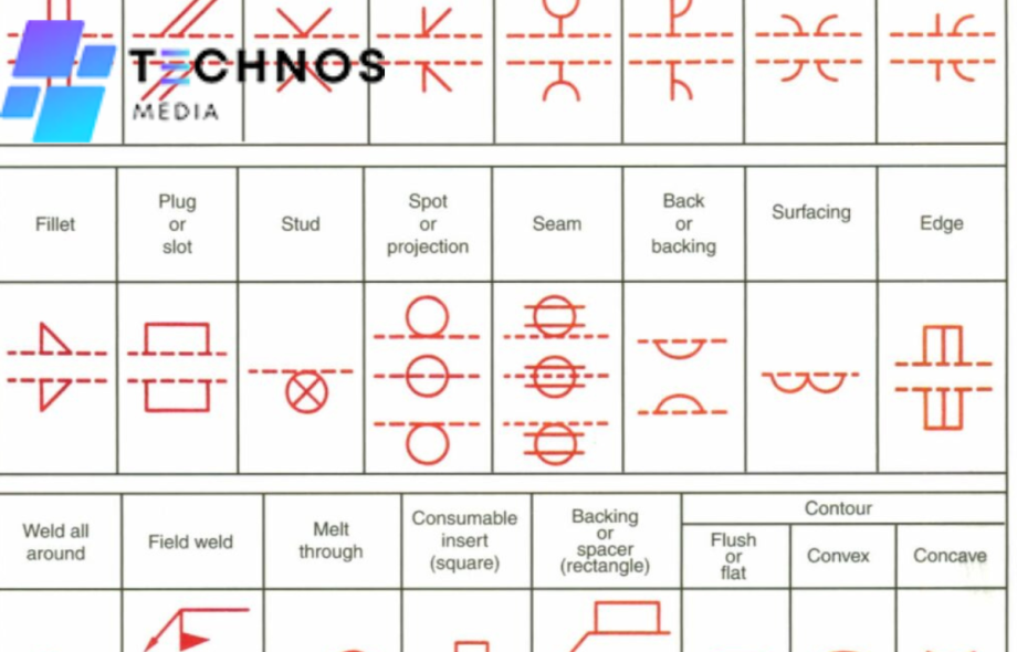
A typical weld symbol consists of several components. The reference line is the main horizontal line where all elements of the weld symbol are placed. The arrow points to the joint where the weld will be applied. Basic weld symbols indicate the type of weld to be performed, such as fillet weld, groove weld, plug or slot weld, and spot or projection weld. Supplementary symbols provide extra details, including contour symbols for convex, concave, or flat finishes, a weld-all-around symbol represented by a circle at the joint, and a field weld symbol indicated by a flag on the reference line. The tail of the weld symbol may contain information about welding processes, specifications, or other requirements.
Common Types of Weld Symbols
Fillet weld symbols are used for corner, T-joints, and lap joints. They are represented by a right-angled triangle placed on the reference line. Fillet welds are commonly used in structural steel fabrication. Groove weld symbols are used when deep penetration is needed. They are represented by a straight line with variations based on the groove type, such as square, V, U, J, or bevel. V-groove welds are often used in thick materials to ensure complete fusion. Plug and slot weld symbols are used to join overlapping metals and are represented by a rectangle with a circle in the center. Plug welds are commonly found in automotive and aerospace industries. Spot and projection weld symbols are used in resistance welding and are represented by a simple circle on the reference line. Projection welds are widely used in sheet metal applications. Seam weld symbols indicate continuous welding along a joint and are represented by a series of dashes along the reference line. Seam welds ensure airtight and watertight connections in piping.
How to Interpret Weld Symbols
To interpret weld symbols, start by identifying the reference line, which serves as the foundation for the weld symbol and helps align the other elements correctly. Observe the arrow placement, which points to the area where the weld is to be applied. If the symbol appears below the reference line, the weld is performed on the arrow side; if above, it is performed on the other side. Recognize the weld type by looking for the specific weld symbol, such as fillet, groove, or plug. Finally, check for dimensions and specifications, including size, length, pitch, and contour symbols, which provide detailed instructions.
Importance of Weld Symbols in the Industry
Weld symbols provide standardized communication, ensuring uniform understanding across engineers, designers, and welders. They help maintain weld integrity and compliance with industry standards, ensuring quality assurance. Weld symbols enhance efficiency in fabrication by reducing misinterpretation and improving workflow in manufacturing. They also ensure safety compliance by guaranteeing that structures and components meet regulatory requirements.
Conclusion
Weld symbols are a fundamental aspect of welding blueprints, providing essential information about the type, size, and location of welds. Mastering these symbols enhances efficiency, ensures compliance with industry standards, and improves communication among professionals. By understanding and interpreting weld symbols correctly, welders and fabricators can execute high-quality and reliable welds in various applications. Whether you are new to welding or an experienced professional, developing a strong grasp of weld symbols will significantly improve your ability to work with technical drawings and achieve precise welds in your projects.
Service/Product Details:
https://technosmedia.com/technology/weld-symbols-chart-know-what-each-symbol-means/